


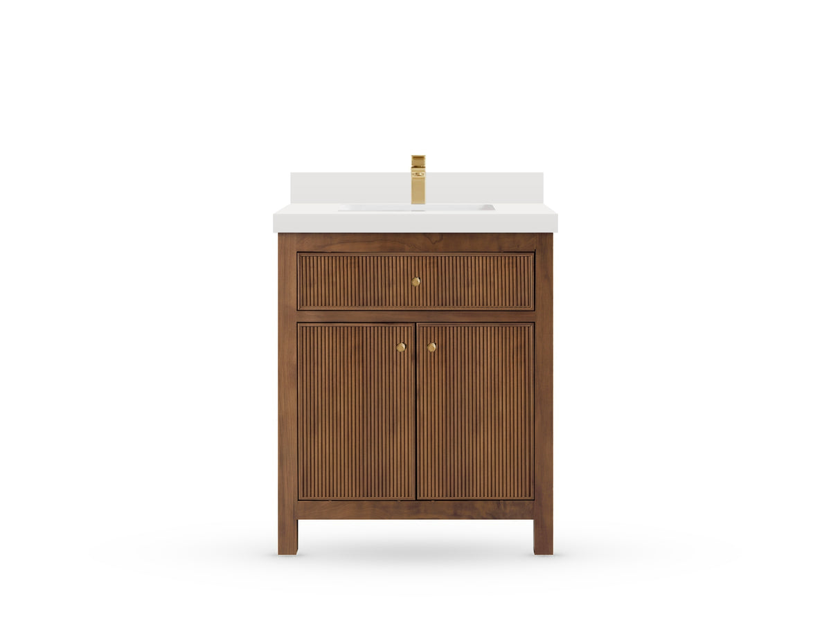
Sonoma Teak 48 vanity - drawing text version
Sonoma Teak 48 vanity - source drawing text version
PDF with text descriptions — 23 pages.
This is a text version of the source drawings. Original drawing images are available through the PDF page links below. Keep the source warnings and unresolved dimensions in mind when using this text version.
All printed dimension labels are preserved without engineering approval. Obtain confirmed dimensions from Willow Bath and Vanity before installation, fabrication, or drilling.
Text equivalent of all ten source pages. Original labels, reference points and alternative countertop styles remain distinct. No dimensions are corrected or approved.
Each source page has its original drawing, a description of the view, and a table identifying what each dimension measures. Inches and millimeters are copied independently from the source; no conversion replaces a printed value.
Source limitations
Inches and millimeters remain separately printed source values. The source does not establish the controlling unit, current approval or included accessories.
The top view shows different upper and lower width references, 47-1/2 in /1208 mm and 47 in /1194 mm. Neither is substituted for the other.
The Double Cove style title says 1.5 IN, while its detailed edge height says 1-5/8 in /40 mm. Both remain as printed.
SON48-P4-UPPER - source page 4
Upper rear band height: 7-7/8 in / 140 mm.
The upper rear band is labeled 7-7/8 in /140 mm. These printed units disagree; a separate opening dimension on this page is 7-7/8 in /200 mm.
Willow Bath and Vanity must confirm the upper-band dimension and both units. No correction has been made.
Source page 1: Sonoma Teak 48 cabinet overview
View original PDF — Source page 1: Sonoma Teak 48 cabinet overview
Original drawing: Sonoma Teak 48 cabinet overview.
Original source page 1, visually unchanged. Read this page's text equivalent.
View and dimensional relationships
Perspective drawing of an open-top cabinet with legs. Broad fluted paired doors and an upper front occupy the center, with three fluted drawer fronts on each side. The open interior shows two drawer boxes and an open central bay. No countertop or separate dimension labels appear here.
Title: SONOMA TEAK 48 IN SINGLE SINK BATHROOM VANITY. Footer: willowbathandvanity.com; info@willowbathandvanity.com; 1-877-788-8444.
No dimension callouts are printed on this overview page.
Source page 2: Cabinet front view
View original PDF — Source page 2: Cabinet front view
Original drawing: Cabinet front view.
Original source page 2, visually unchanged. Read this page's text equivalent.
View and dimensional relationships
A central paired-door bay and upper front are flanked by two narrow three-drawer columns. Round knobs are visible on doors and drawers, with outer legs and smaller intermediate supports below the rail. The upper width labels separately identify the main cabinet and small projections at both sides.
On a narrow screen, scroll the measurement table horizontally to read every column. With a keyboard, focus the table region and use the left and right arrow keys.
| Measurement | Inches | Millimeters | Reference points / meaning |
|---|---|---|---|
| Main cabinet width | 47 | 1194 | Upper horizontal span between the outer frame faces, excluding separately labeled small projections. |
| Left side projection | 1/4 | 5 | Upper left short horizontal span outside the main frame. |
| Right side projection | 1/4 | 5 | Upper right short horizontal span outside the main frame. |
| Overall cabinet height | 34 | 865 | Full vertical span at the left to the foot reference. |
| Right upper drawer front height | 6-1/4 | 160 | Upper right vertical dimension across the top narrow front. |
| Right middle drawer front height | 6-1/4 | 160 | Middle right vertical dimension across the second narrow front. |
| Right lower drawer front height | 11-3/8 | 290 | Right vertical dimension across the tall lower narrow front. |
| Foot clearance below rail | 3-3/4 | 95 | Lower right vertical span from the bottom rail reference to the feet. |
Source note: The source states: All measurements are plus or minus 1/4 inch. Values remain as printed, not converted or approved for installation.
Source page 3: Cabinet top view
View original PDF — Source page 3: Cabinet top view
Original drawing: Cabinet top view.
Original source page 3, visually unchanged. Read this page's text equivalent.
View and dimensional relationships
The plan shows two narrow side drawer bays and a wide central bay with a U-shaped recess. The uppermost width is drawn to wider outside references than the lower overall width; both labels remain distinct. Additional dimensions identify inner bays, a side drawer width and a central lower internal span.
On a narrow screen, scroll the measurement table horizontally to read every column. With a keyboard, focus the table region and use the left and right arrow keys.
| Measurement | Inches | Millimeters | Reference points / meaning |
|---|---|---|---|
| Upper outside reference width | 47-1/2 | 1208 | Topmost horizontal span to the widest indicated side references; not substituted for the lower width. |
| Left inner bay width | 10-3/8 | 263 | Upper left inner horizontal span. |
| Central inner bay width | 20 | 508 | Upper central inner horizontal span. |
| Right inner bay width | 10-3/8 | 263 | Upper right inner horizontal span. |
| Overall cabinet depth | 21-1/2 | 545 | Full outside vertical span at the left. |
| Left drawer interior width | 7-7/8 | 199 | Horizontal span across the interior of the left drawer box. |
| Central lower interior width | 18 | 458 | Horizontal span above the lower central internal edge. |
| Left outer member width | 2 | 50 | Bottom left short horizontal span. |
| Lower inner width | 43-1/8 | 1094 | Lower horizontal span between inner side-member references. |
| Right outer member width | 2 | 50 | Bottom right short horizontal span. |
| Lower overall cabinet width | 47 | 1194 | Bottommost horizontal span between the main outer frame references. |
Source note: The source states: All measurements are plus or minus 1/4 inch. Values remain as printed, not converted or approved for installation.
Source page 4: Cabinet back view
View original PDF — Source page 4: Cabinet back view
Original drawing: Cabinet back view.
Original source page 4, visually unchanged. Read this page's text equivalent.
View and dimensional relationships
An upper horizontal rear band sits above three vertical rear regions. A rectangular opening lies in the middle region. The top and bottom width chains and opening offsets use separate reference lines. The upper-band inch/mm pair is retained but flagged for confirmation.
On a narrow screen, scroll the measurement table horizontally to read every column. With a keyboard, focus the table region and use the left and right arrow keys.
| Measurement | Inches | Millimeters | Reference points / meaning |
|---|---|---|---|
| Upper inner width | 43-1/8 | 1094 | Upper horizontal span between the inner side-member references. |
| Left upper member width | 2 | 50 | Upper left short horizontal span. |
| Right upper member width | 2 | 50 | Upper right short horizontal span. |
| Overall cabinet height | 34 | 865 | Full vertical outside span on the left. |
| Left rear region width | 8-5/8 | 218 | Horizontal span above the left rear region. |
| Central rear region width | 19-5/8 | 498 | Horizontal span above the central rear region. |
| Right rear region width | 8-5/8 | 218 | Horizontal span above the right rear region. |
| Upper rear band height: unresolved | 7-7/8 | 140 | Right vertical span from cabinet top to the underside of the upper band. The printed inch/mm pair conflicts.Unresolved: SON48-P4-UPPER |
| Lower rear region height | 22-7/8 | 580 | Right vertical span from underside of upper band to top of bottom rail. |
| Central left edge to opening | 5-7/8 | 149 | Horizontal offset from central rear region left boundary to opening left edge. |
| Rear opening width | 7-7/8 | 200 | Horizontal span above the rectangular opening. |
| Upper band to opening top | 5-3/8 | 138 | Vertical offset from underside of upper band to opening top. |
| Rear opening height | 7-7/8 | 200 | Vertical span at the right of the rectangular opening. |
| Overall rear width | 47 | 1194 | Bottom horizontal span between outside frame references. |
Source note: The source states: All measurements are plus or minus 1/4 inch. Values remain as printed, not converted or approved for installation.
Source page 5: Cabinet side view
View original PDF — Source page 5: Cabinet side view
Original drawing: Cabinet side view.
Original source page 5, visually unchanged. Read this page's text equivalent.
View and dimensional relationships
The side panel is framed by two end members and upper/lower rails. The left edge shows front hardware projections. Separate dimensions identify a small projection, panel/rail depths and the lower foot clearance.
On a narrow screen, scroll the measurement table horizontally to read every column. With a keyboard, focus the table region and use the left and right arrow keys.
| Measurement | Inches | Millimeters | Reference points / meaning |
|---|---|---|---|
| Overall cabinet depth | 21-1/2 | 545 | Upper outside horizontal span. |
| Front projection | 1/4 | 5 | Short horizontal span at the upper left beyond the main frame. |
| Left end member depth | 2 | 50 | Upper left segment inside the overall depth chain. |
| Side panel depth | 17-1/2 | 445 | Upper middle segment across the inset panel. |
| Right end member depth | 2 | 50 | Upper right segment of the depth chain. |
| Upper rail height | 2 | 50 | Top left vertical segment. |
| Side panel height | 26-3/8 | 670 | Middle left vertical segment. |
| Lower rail height | 2 | 50 | Short lower left vertical segment above the feet. |
| Foot clearance | 3-3/4 | 95 | Lowest left vertical span. |
| Overall cabinet height | 34 | 865 | Full outside vertical span at the right. |
Source note: The source states: All measurements are plus or minus 1/4 inch. Values remain as printed, not converted or approved for installation.
Source page 6: 48 inch Straight Mitered Edge countertop overview
View original PDF — Source page 6: 48 inch Straight Mitered Edge countertop overview
Original drawing: 48 inch Straight Mitered Edge countertop overview.
Original source page 6, visually unchanged. Read this page's text equivalent.
View and dimensional relationships
Perspective drawing of a countertop with one central rounded rectangular sink opening, one faucet hole, a flat rear backsplash and a straight edge. The title identifies 48 IN SINGLE SINK 2 IN STRAIGHT MITERED EDGE COUNTERTOP. No separate dimension callouts appear here.
No dimension callouts are printed on this overview page.
Source page 7: Straight Mitered Edge countertop dimensions
View original PDF — Source page 7: Straight Mitered Edge countertop dimensions
Original drawing: Straight Mitered Edge countertop dimensions.
Original source page 7, visually unchanged. Read this page's text equivalent.
View and dimensional relationships
Separate backsplash elevations appear above a straight front edge elevation and a plan. The plan locates one faucet hole, the central opening and four bracket holes; SINK BRACKET points to one hole. Two leaders state 45 Degree Mitered Edge. The source note limits these dimensions to this style and refers the other style to the Double Cove Edge section.
On a narrow screen, scroll the measurement table horizontally to read every column. With a keyboard, focus the table region and use the left and right arrow keys.
| Measurement | Inches | Millimeters | Reference points / meaning |
|---|---|---|---|
| Backsplash width | 48 | 1220 | Horizontal full span of the backsplash elevation. |
| Backsplash height | 3-7/8 | 100 | Vertical height of the backsplash elevation. |
| Backsplash thickness | 3/4 | 20 | Thickness of the separate side profile. |
| Mitered edge height | 2 | 50 | Vertical height of the straight edge elevation. |
| Left edge wall thickness | 3/4 | 20 | Short horizontal segment at left end of edge elevation. |
| Right edge wall thickness | 3/4 | 20 | Short horizontal segment at right end of edge elevation. |
| Plan outside width | 48 | 1220 | Full horizontal outside span of the countertop plan. |
| Left edge to faucet center | 24 | 610 | Upper left horizontal segment to the faucet centerline. |
| Faucet center to right edge | 24 | 610 | Upper right horizontal segment from the faucet centerline. |
| Plan outside depth | 22 | 560 | Full vertical outside span at the left. |
| Rear edge to sink opening | 5-1/2 | 140 | Upper segment of the left opening chain. |
| Sink opening depth | 12-1/4 | 310 | Middle segment of the left opening chain. |
| Sink opening to front edge | 4-3/8 | 110 | Lower segment of the left opening chain. |
| Rear edge to faucet center | 2-3/4 | 70 | Short vertical offset to the faucet hole center. |
| Faucet-hole diameter | 1-3/8 | 35 | Diameter leader attached to the round faucet hole. |
| Rear edge to bracket row | 6-3/4 | 170 | Upper segment of the internal right vertical bracket chain. |
| Bracket row spacing | 9-7/8 | 250 | Middle segment between rear and front bracket-hole rows. |
| Front bracket row to front edge | 5-1/2 | 140 | Lower segment of the bracket chain. |
| Left edge to opening | 15-3/8 | 390 | Left segment of the lower horizontal opening chain. |
| Sink opening width | 17-3/8 | 440 | Middle segment of the opening chain. |
| Opening to right edge | 15-3/8 | 390 | Right segment of the opening chain. |
| Left edge to bracket column | 13-1/8 | 333 | Left segment of the bottom horizontal bracket chain. |
| Bracket column spacing | 21-3/4 | 554 | Middle span between left and right bracket columns. |
| Bracket column to right edge | 13-1/8 | 333 | Right segment of the bottom bracket chain. |
| Separate edge section width | 2 | 50 | Horizontal span above the narrow right edge section. |
| Separate edge upper wall | 3/4 | 20 | Upper short vertical segment of the right edge section. |
| Separate edge lower wall | 3/4 | 20 | Lower short vertical segment of the right edge section. |
| Opening corner label 4-R10 | Not printed separately | Not printed separately | Corner leader states 4-R10 without a separate unit. |
Source note: The source states: All measurements are plus or minus 1/4 inch. Values remain as printed, not converted or approved for installation.
Source page 8: Standard rectangular undermount sink
View original PDF — Source page 8: Standard rectangular undermount sink
Original drawing: Standard rectangular undermount sink.
Original source page 8, visually unchanged. Read this page's text equivalent.
View and dimensional relationships
The left drawing shows the rectangular rim and the bowl inside it. The hatched band is outside the inner opening. Sloping walls run from that opening toward the bowl floor. Two unlabeled apertures are shown along the centerline; this page does not give their diameters.
The right drawing is a side section of the same sink. Its height label is a sectional outside measurement as drawn, not a separately labeled usable water depth. The countertop cutout dimensions appear on pages 7 and 10 and are different from the sink dimensions on this page.
On a narrow screen, scroll the measurement table horizontally to read every column. With a keyboard, focus the table region and use the left and right arrow keys.
| Measurement | Inches | Millimeters | Reference points / meaning |
|---|---|---|---|
| Outside rim width | 20-1/8 | 511 | Left-to-right span across the outside edges of the hatched rim. |
| Outside rim depth | 15 | 381 | Front-to-back span across the outside edges of the rim. |
| Inner opening width | 17-3/4 | 451 | Left-to-right span at the inner edge of the rim, above the sloping bowl walls. |
| Inner opening depth | 12-5/8 | 320.6 | Front-to-back span at the inner edge of the rim. |
| Section height | 7-5/8 | 193.6 | Vertical dimension of the side section, between the upper and lower reference lines shown. |
Source note: The source states: All measurements are +/- 1/4 inch. Values below are transcribed, not recalculated or approved for installation.
Source page 9: 48 inch Double Cove Edge countertop overview
View original PDF — Source page 9: 48 inch Double Cove Edge countertop overview
Original drawing: 48 inch Double Cove Edge countertop overview.
Original source page 9, visually unchanged. Read this page's text equivalent.
View and dimensional relationships
Perspective drawing of a single-opening countertop with one faucet hole, a molded rear backsplash and stepped front/side edges. Title: 48 IN SINGLE SINK 1.5 IN DOUBLE COVE EDGE COUNTERTOP. No separate dimension callouts appear here.
No dimension callouts are printed on this overview page.
Source page 10: Double Cove Edge countertop dimensions
View original PDF — Source page 10: Double Cove Edge countertop dimensions
Original drawing: Double Cove Edge countertop dimensions.
Original source page 10, visually unchanged. Read this page's text equivalent.
View and dimensional relationships
A molded backsplash front/side elevation and layered edge elevation appear above the plan. The plan locates the central opening, faucet hole, bracket holes and inset bands. A separate narrow edge section is at the right. The source note says these dimensions apply exclusively to Double Cove Edge countertops and refers the other style to the Straight Mitered Edge section.
The title says 1.5 IN, while the detailed edge height is 1-5/8 in /40 mm. Both remain separate printed labels.
On a narrow screen, scroll the measurement table horizontally to read every column. With a keyboard, focus the table region and use the left and right arrow keys.
| Measurement | Inches | Millimeters | Reference points / meaning |
|---|---|---|---|
| Backsplash width | 45-7/8 | 1166 | Full horizontal span of the molded backsplash elevation. |
| Backsplash height | 3-7/8 | 100 | Vertical height of the backsplash elevation. |
| Backsplash thickness | 3/4 | 20 | Thickness of the separate side profile. |
| Cove edge height | 1-5/8 | 40 | Full vertical span of the layered edge elevation. |
| Cove edge upper segment | 3/4 | 20 | Upper short vertical segment at the right end of the edge elevation. |
| Cove edge lower segment | 3/4 | 20 | Lower short vertical segment at the right end of the edge elevation. |
| Plan outside width | 48 | 1220 | Full horizontal outside span of the countertop plan. |
| Left edge to faucet center | 24 | 610 | Upper left horizontal segment to the faucet centerline. |
| Faucet center to right edge | 24 | 610 | Upper right horizontal segment from the faucet centerline. |
| Plan outside depth | 22 | 560 | Full vertical outside span at the left. |
| Rear edge to sink opening | 5-1/2 | 140 | Upper segment of the left opening chain. |
| Sink opening depth | 12-1/4 | 310 | Middle segment of the left opening chain. |
| Sink opening to front edge | 4-3/8 | 110 | Lower segment of the left opening chain. |
| Rear edge to faucet center | 2-3/4 | 70 | Short vertical offset to the faucet hole center. |
| Faucet-hole diameter | 1-3/8 | 35 | Diameter leader attached to the round faucet hole. |
| Rear edge to bracket row | 6-3/4 | 170 | Upper segment of the internal right vertical bracket chain. |
| Bracket row spacing | 9-7/8 | 250 | Middle segment between rear and front bracket-hole rows. |
| Front bracket row to front edge | 5-1/2 | 140 | Lower segment of the bracket chain. |
| Left edge to opening | 15-3/8 | 390 | Left segment of the lower horizontal opening chain. |
| Sink opening width | 17-3/8 | 440 | Middle segment of the opening chain. |
| Opening to right edge | 15-3/8 | 390 | Right segment of the opening chain. |
| Left edge to bracket column | 13-1/8 | 333 | Left segment of the bottom horizontal bracket chain. |
| Bracket column spacing | 21-3/4 | 554 | Middle span between left and right bracket columns. |
| Bracket column to right edge | 13-1/8 | 333 | Right segment of the bottom bracket chain. |
| Rear inset band | 1 | 25 | Short vertical distance from rear outside edge to rear dashed inset line. |
| Right inset band | 2 | 50 | Short horizontal distance across the right inset band. |
| Front inset band | 2 | 50 | Short vertical distance across the front inset band. |
| Separate edge section width | 1-5/8 | 40 | Horizontal span above the narrow right edge section. |
| Opening corner label 4-R20 | Not printed separately | Not printed separately | Corner leader states 4-R20 without a separate unit. |
Source note: The source states: All measurements are plus or minus 1/4 inch. Values remain as printed, not converted or approved for installation.
Source and assistance
View the original source PDF. Source reviewed 19 November 2026.
Request an accessible format or a confirmed drawing, or call Willow Bath and Vanity at (877) 788-8444.